
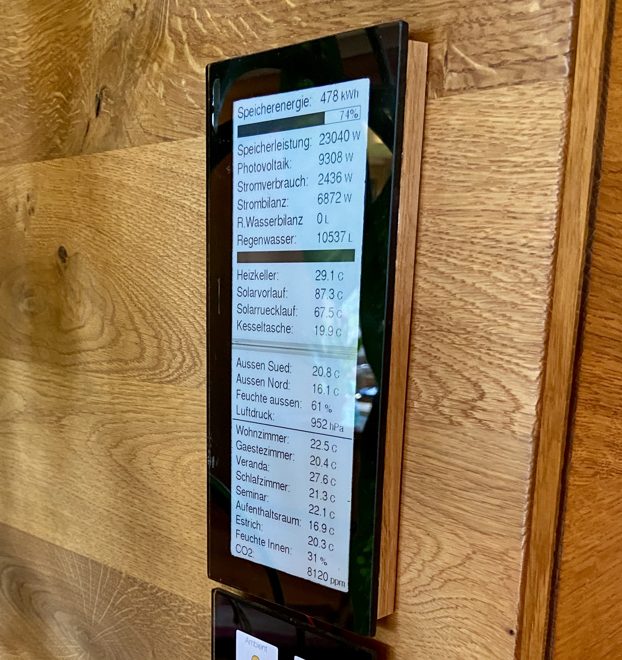
This is a short tutorial on how to make an E-Ink display / E-Paper display to display KNX values. The display here is bus powered and refreshes it’s values every 3 minutes. It has been running for a year without a single freeze or any other problem.
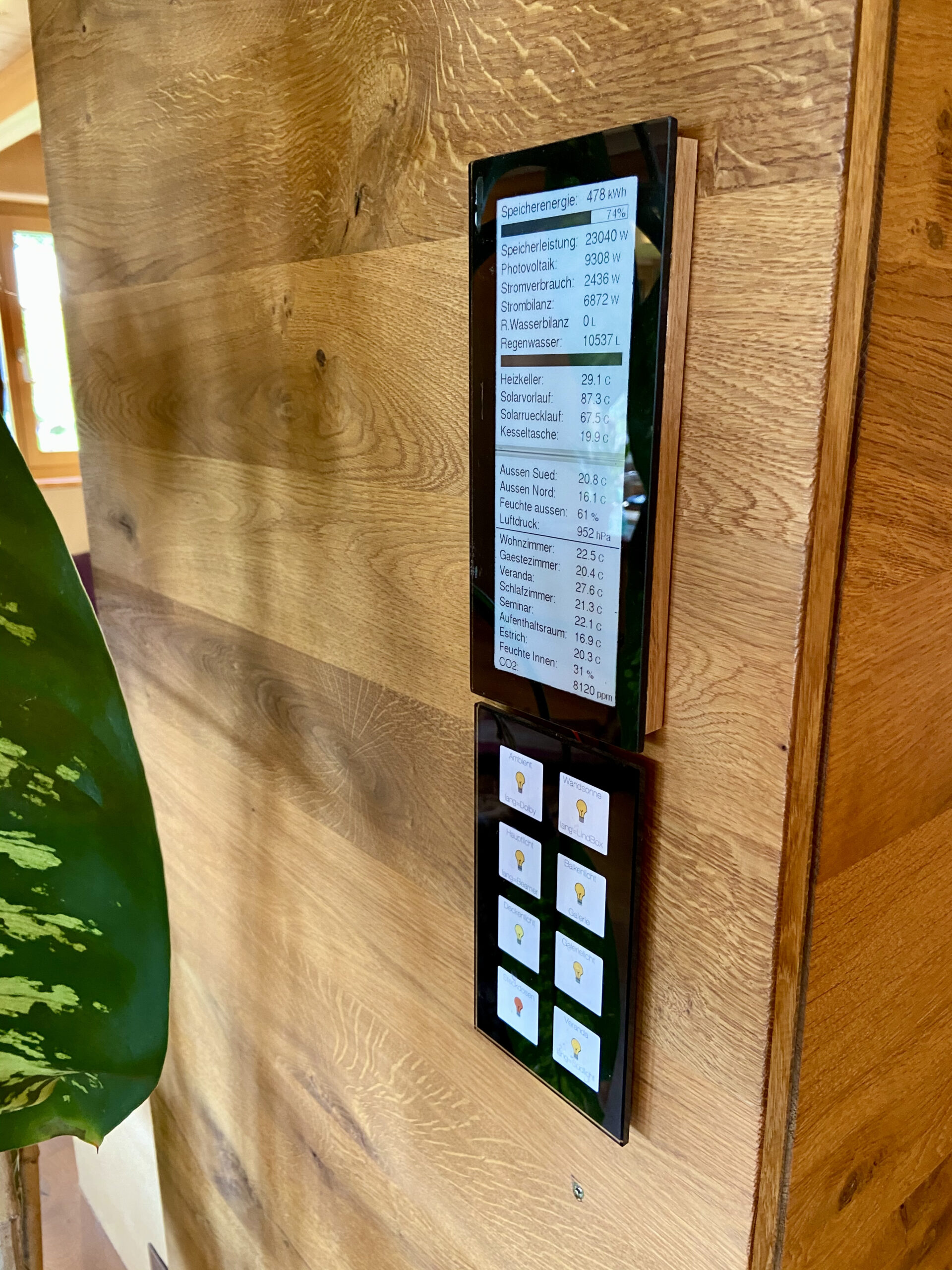
Two 4.2″ E-Paper displays (also called EPD or E-Ink displays) are connected via a control board to one Arduino Pro Mini, which is in turn connected to a KNX Bus coupler. The cost for the materials are about 120€. The KNX bus coupler as well as each of the display are around 30€, the two control boards for the EPD-Displays are about 8€ each and the rest of the parts are cheap.
The individual changes you need to do to the code are not small, but not a lot either. I wouldn’t say this is an easy project for a beginner. But if you have a bit of experience with problem solving, Arduino and soldering this is doable. There are some very my-project-specific parts in the code which you can remove and greatly simplify. But I left the code as is, since it might give you more insight for your own customizations.
EPDs do NOT glow or light up in any way. This is great if you don’t want to have glowy things in your house. The display integrates much better with natural materials than a displays with LED and stuff. My wife would never allow me to use a display which glows in the dark. Any useless LEDs will be covered or dismantled in our house immediately. However this display, she accepted right away. And to be honest, I also don’t like stuff that glows, anymore. I made our house very smart over the years, but apart from what you see bellow, it is completely hidden underneath a rustic look. All the technology is stashed away in one room. I love this: HighTech hidden in Lowtech. But, it’s a matter of taste 🙂
E-Ink display / E-Paper displays need almost no power to keep their image. In fact the ones I used here theoretically don’t need any power at all to keep the image visible! The images stays, when power is off. The background will fade into gray a bit only after multiple days without power. Since, obviously, new values should be shown on the display, refreshing is being done, so this is not an issue. The refresh itself needs a bit of energy but it’s less than 30mW at 3.3V for 5 seconds, so less than 10mA. The energy consumption for this is less than 0.00005Wh. In addition the continuous power needed is 0.017mW, which is negligible.
I refresh the displays every 3 Minutes, so 20 refreshes an hour, which puts energy consumption at less than 0.0009Wh per hour or 0.02Wh per day or 7.5Wh per year. To put that in perspective, the Arduino pro mini used to control the display needs roughly 5mA at 3.3V, so 16mW or 150 Wh of energy per year. The E-ink displays are in comparison wildly efficient. Even when useing two of them on one Arduino we are only needing 170Wh per year. The power cost for about 170Wh (0.17kwh) is, depending on where you live, around 2-10 cents.
Why do I not refresh the KNX Epaper display quicker than every 3 Minutes? Because it is the minimum time recommended for E-paper in order to keep them healthy for a long time. They don’t like quicker refresh rates. Thus: this is not suited for realtime display of quickly changing values. This is a low power solution for a display that stays always on.
What you need:
- Siemens KNX Bus coupler
- Arduino Pro Mini 3.3V (ProMicro 3.3V, Uno will probably also work, but minimal changes in code might be needed. I used the pro mini 3.3V because power consumption is very low, and I didn’t find any reliable data for the ProMicro)
- FTDI Adapter to connect the Arduino Mini to your computer for programming. (Only if you use the Arduino Mini). Here you can get the FTDI and the ProMini at once.
- Angled header
- Some sort of cable/connector. But you can also just solder it directly to the arduino.
- Waveshare E-Paper display 4.2 inch. (One or two pieces depending on your solution), Three color version also works, but has 3x longer refresh times.
- Adafruit eInk breakout friend. To connect the display to the arduino (two for two displays).
- If you don’t use the Adafruit E-ink friend you can also use the adapter from Waveshare or use a Waveshare display with breakout board (depending on the space you have), but this will need changes in the code. I have not tried this and have no experience.
- Soldering Iron
- Voltmeter
Disclaimer: If you use the links above, I get a very small percentage from Amazon. Thank you for your support of future tutorials.
A KNX E-Paper display – But why?
As you can see above, the power consumption of an E-Paper / eInk display is ridiculously low. Also it doesn’t emit any light. If you don’t want to have any glowy things that eat up power all day long, but still want to display values of your home somewhere, this is the best solution.
Basic Considerations
Arduino power
The Arduino draws its power from the KNX bus coupler. The 5WG1 117-2AB12 bus couplers data sheet says it can deliver a maximum of 10mA on the 5V output. The Arduino pro mini 3.3 V draws up to 5mA on its own plus 10mA for about 5 seconds when one display refreshes. Even though this exceeds the specifications of the coupler it works well. Many others have reported it works even with a lot more power drawn. Some even tested it up to 20mA continuously with success. However, I recommend to be cautious.
Two displays
I like it 🙂 It is important to refresh the two displays 10 seconds apart, to distribute power draw.
Steps, rough overview:
- Disassemble the case of the bus-coupler, if you can’t use it the way it is, like me. Otherwise, leave it like that.
- Solder 4 wires to the angled header in order to connect to the bus coupler, (pins as described bellow).
- Solder 4 wires to the Arduino, (pins as described bellow).
- If you want use connector cable instead of direct wire.
- Solder cables to Adafruit eInk breakout friend and to the Arduino. (pins like here).
- Plug in the eInk display into the eInk breakout friend.
- Edit Arduino Code to your specifications.
- Programm Arduino (Buscoupler MUST NOT be connected, while programming)
- Make a case / box / glaspanel whatever to mount the display.
Connections for KNX E-Paper display
Bus coupler to Arduino
Thanks to this tutorial connecting is simple :
| Arduino | Bus coupler |
|---|---|
| GND | GND (PIN 1) |
| RAW | 5V VCC (PIN 5) |
| RX | TX (PIN 4) |
| TX | RX (PIN 2) |
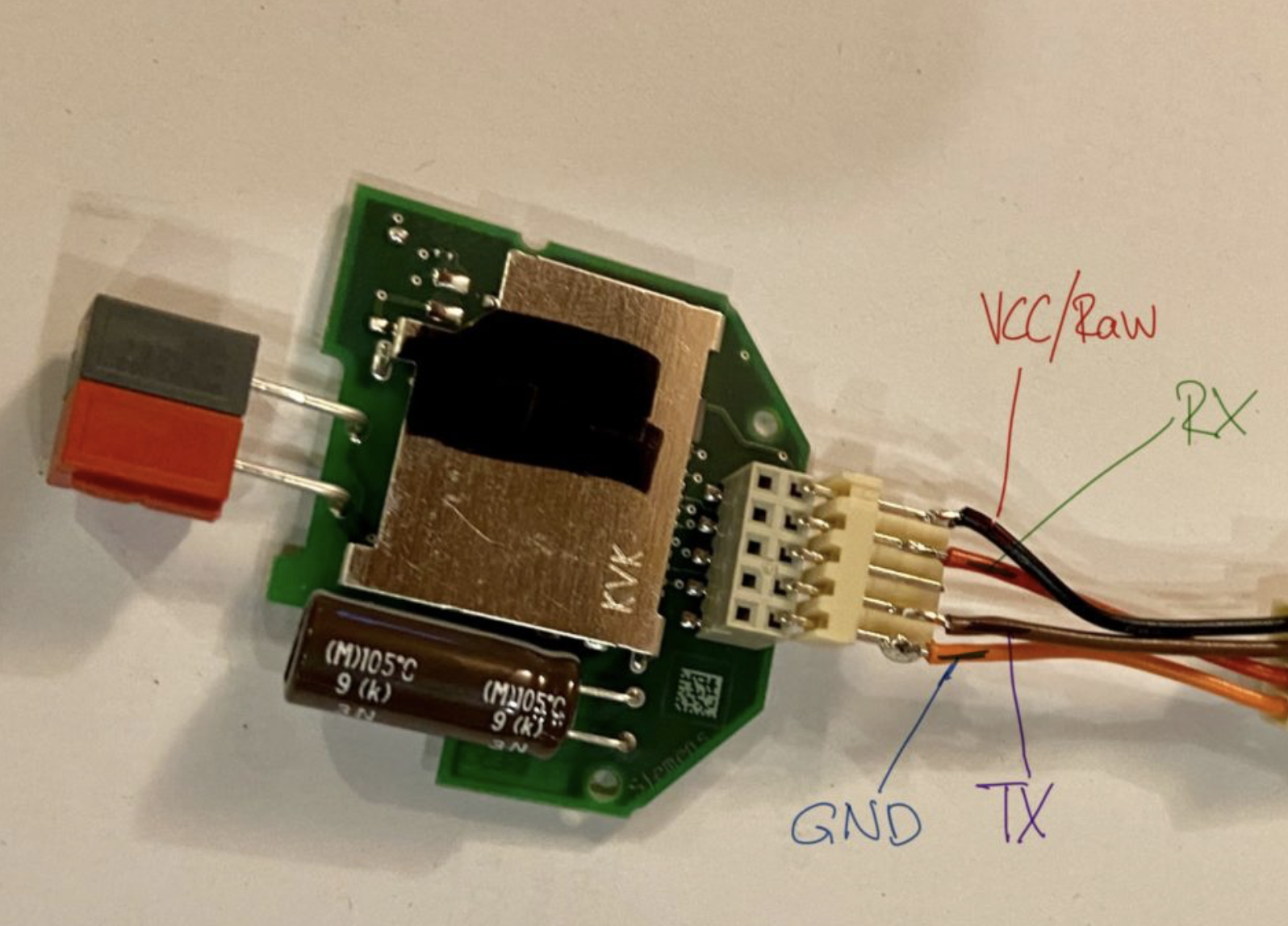
Arduino Siemens KNX Buscoupler Connection
Software
Other people have done amazing work with the libraries and tutorials. This OneWire to KNX Bridge is only possible thanks to them and I am very grateful for that. In this case the people in the KNX-Userforum and the authors of libraries like the KNX library.
For the E-Paper / E-Ink display you need the Adafruit_GFX.h library, and the Adafruit_EPD.h library which you both can install directly from the library manager in the Arduino IDE. (Tools – Manage Libraries – Search for it, click install)
Edit the software to your needs – these are the steps, if you use two displays:
- Edit “Address of this KNX device” to your desired address.
- Define all the KNX addresses that you are going to read from the KNX-Bus. Do this according to the the addresses you are using in your system. These are your address-definitions.
- Edit the array groups to your needs. All the values as well as all other things that will be displayed or configure how to display a certain value are stored in groups of arrays. First count the number of values you are going to read from KNX and display on the displays. Second split those values into groups of a maximum of 10. Now edit / delete groups to fit your setup. You will make life much easier to you, if you sort the variables into the array into the order in which they are displayed on the display top to bottom.
The adaption of each array group contains five steps:- Adapt the first array to the Address-Definitions you did in step 2.
- Adapt the second array to the texts that have to be displayed left of the values.
- Adapt the third array to the units that have to be displayed right of the values.
- Adapt the fourth array to the number of digits after the comma to bis displayed for each value.
- Set the value array to the correct size. If you have 5 values, write 5 into the [] brackets.
- Edit lines 160 to 178. Here the KNX addresses to be listened to are being set with “for-loops”. The is one “for-loop” for each array group. You need the the number of loops according to the array size. Since an array of length “5” has a position “0”, the highest position is “4”. Therefore the for-loop which processes an array with the length 5 will have the setting “int i = 0; i <= 4; i = i + 1”
- If you read more than 15 values from KNX you need to change this limit in the KnxTpUart.h library on line 41 “MAX_LISTEN_GROUP_ADDRESSES 15”.
- Next you need to adapt from around line 200 to 270. This controls what is actually written to the display. Basically this is all done through the “WriteEPD1”, “WriteEPD2” functions. How to use them is commented in the code. Please beware, that the example code has quite some specialities and thus the variables are not just listed in order. If you defined your arrays in the exact order your values should be displayed top to bottom on the display, then you can actually do all the displaying with just one call of the function per array. Like so:
for (int i = 0; i <= 9; i = i + 1) {
      WriteEPD1(i + 1 , TextToBeDisplayedArray[i], ValueToBeDisplayedArray[i], UnitArray[i], NumberOfDigitsArray[i], -3);
    }
The above code would display 10 texts, values and units from one array-group, top to bottom starting from line 1 of the display.
- Adapt the “maintainKNXSerial” function. This functions grabs the data from KNX. For each array there is one for-loop. However in the example code one group is processed in a special way, because it contains some special values that need special processing. You can ignore that. The main way to get the values for an array-group is this:
for (int i = 0; i <= 9; i = i + 1) {
if (target == ArrayOfKNXAdresses[i]) {
ValueToBeDisplayed[i] = telegram->get2ByteFloatValue(); } }
This grabs 10 values from the KNX bus. It uses 10 KNX addresses which are stored in “ArrayOfKNXAddresses” and stores the values in the array “ValueToBeDisplayed”.
- Remove code that you don’t need. For example the charge/fill bars or the separation lines. Or adapt it to your needs.
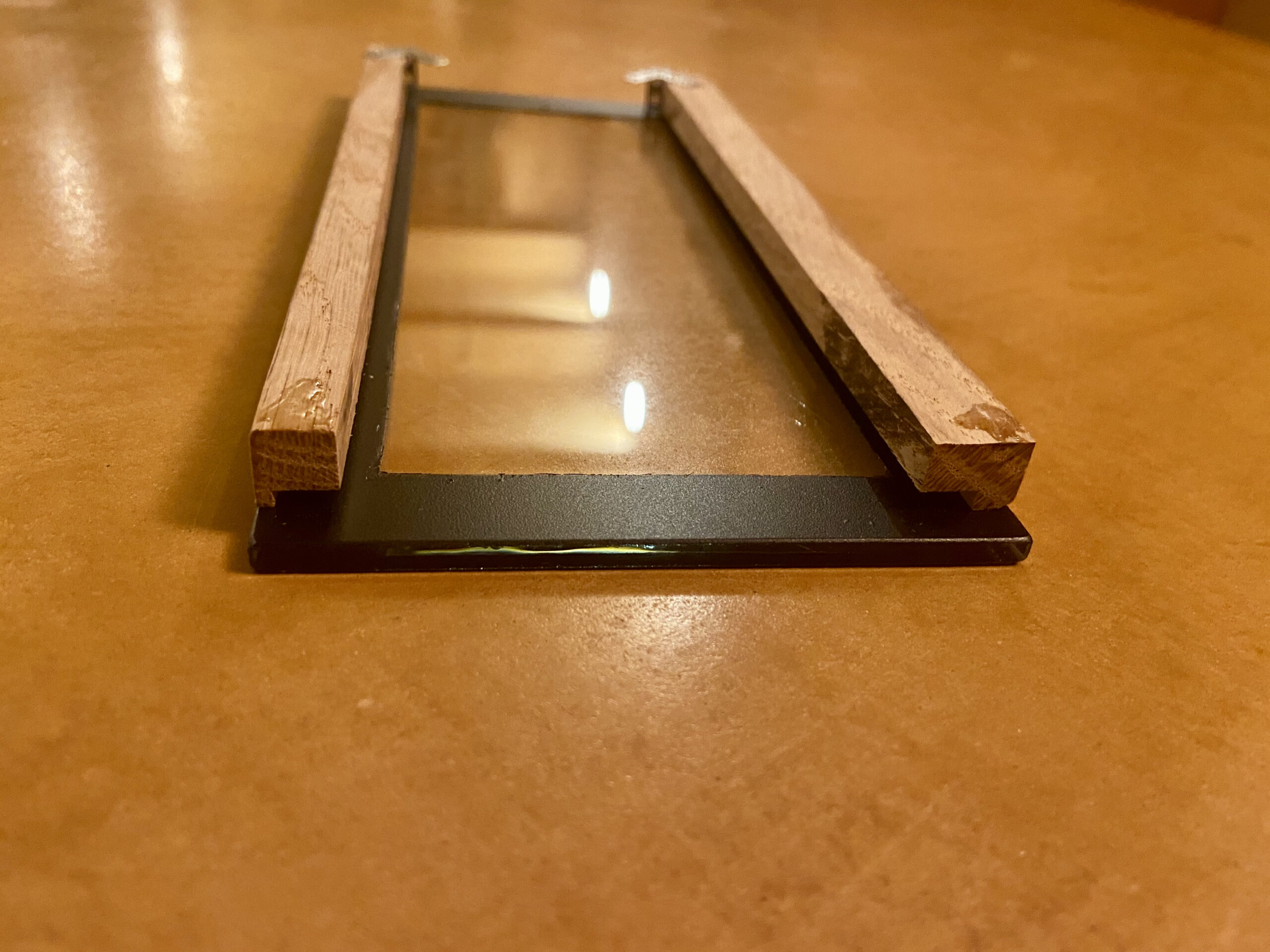
Create some kind of enclosure
I ordered a piece of glas in the dimensions 92mm x 205mm, thickness 4mm. If you use only one display and want to match the MDT glas push button you would probably need something like 92mm x 114mm.
Then I spray painted black borders to it, to match the style of the MDT glas push button BE-GTT8W.01 which I use. Then I took two pieces of 1x1cm oak and cut them into length as well gave them an “L” shape, sort of. Those pieces I glued to the back of the glas.
The displays then slid between the glas and the wood. The Bus coupler was positioned inside the wall box of the MDT switch, while the arduino and the EPD control board fit behind the display.
Two tiny metal brackets were glued to the top. The display is “hanged” to the wall by two tiny nails.
The Code KNX_EPD_Display_V3.7.ino
// #include <Arduino.h>
#include <KnxTpUart.h>
#include <Adafruit_GFX.h>    // Core graphics library
#include "Adafruit_EPD.h"
#include "Fonts/FreeSans9pt7b.h"
#include "Fonts/FreeSans12pt7b.h"
#include "Fonts/FreeMono9pt7b.h"
#include "Fonts/FreeMono12pt7b.h"
#include "Fonts/Org_01.h"


// Text Styles for Sizes
#define smallfont &FreeSans9pt7b
#define bigfont &FreeSans12pt7b

// Text colors / Change colorblack to "EPD_BLACK" if you use a multi colour display
// For some reason of the library the 1-colour display reacts to "EPD_RED" with black colour.
#define colorred EPD_RED
#define colorblack EPD_RED

// Text columns definition. Chance this if you want the columns to be different.
#define column1 10
#define column2 205


// EPD Pins Display 1
#define EPD_CS1     10
#define EPD_DC1     9
#define SRAM_CS1    8
#define EPD_RESET1   7

// EPD Pins Display 2 - if you use only one display, this can be removed. The rest of the pins are shared between the two displays.
#define EPD_CS2     6
#define EPD_DC2     5
#define SRAM_CS2    4
#define EPD_RESET2   3

// Address of this KNX device
#define PHYSICAL_ADDRESS "5.0.31"

// KNX Addresses definitions - Define your own addresses - Make sure the variables match in the code
// Use the replace function to replace all instances in the code. For example replace all "AWirkleistung" with
// whatever variable you are using. For example "ATemperatureLivingRoom".
// The names used here, are specific to my project. They make no sense anywhere else.

#define AWirkleistung "5/1/13"
#define AVerbrauch "5/1/22"
#define AWechselrichterleistung "5/0/11"
#define ASpeicherEnergie "2/7/12"
#define ASpeicherleistung "5/1/23"

#define AWaterCycle "5/0/19"
#define ARegenwasser "5/0/8"
#define ATSolarRL "2/7/1"
#define ATSolarVL "2/7/0"
#define ATKesseltasche "2/7/11"
#define ATHeizkeller "2/5/16"

#define AHEsszimmerArdu "5/0/41"
#define APressure "5/0/42"
#define AeCO2 "5/0/44"

#define ATAussenSued "2/5/14"
#define ATAussenNord "2/5/13"
#define AHAussenNord "2/6/13"
#define ATWohnzimmer "2/5/4"
#define ATGaestezimmer "2/5/1"
#define ATVeranda "2/5/5"
#define ATSchlafzimmer "2/5/24"
#define ATSeminar "2/5/18"
#define ATAufenthaltsraum "2/5/28"
#define ATEstrich "2/5/11"

// Here Variables to display are organized in 4 groups, each group needs 5 arrays.
// The first array of each group is for the KNX address
// The second array of each group is the string that will be displayed on the display.
// The third array of each group is the unit of the displayed value
// The forth array of each group is the number of digits after the comma, that will be displayed.
// The fifth array of each group is the array to which the KNX Values will be stored after they are received.
// The order of the values has to be the same in each array.

// Please note: An array has a position 0 (Zero). It also has a length (number of places for values to be stored in)
// An array with this content: DEMO[] = {A, B, C, D, E} has a length of 5 (Five)
// BUT! The positions of the same array have numbers 0 - 4 (Four).
// If you want to get the "E" from the array, which is the FIFTH value, you get it like this DEMO[4].
// This can sometimes be confusing. When you adapt this code you always need to be aware of this.
// In the comments of the code sometimes the array "position" is mentioned. Positions start with 0.

// Variable Group 1 (in this case, all variables that are about power)
char const *AdressVarLeis[] = {ASpeicherEnergie, ASpeicherleistung, AWechselrichterleistung, AVerbrauch, AWirkleistung};
char const *TextVarLeis[] = {"Speicherenergie:", "Speicherleistung:", "Photovoltaik:", "Stromverbrauch:", "Strombilanz:"};
char const *UnitVarLeis[] = {" kWh", " W", " W", " W", " W"};
int DigitVarLeis[] = {0, 0, 0, 0, 0};
volatile float ValueVarLeis[5]; // The number has to be the number of values that will be stored in here.


// Variable Group 2 (in this case, all variables that are about Temperatures of the heating system)
char const *AdressVarHeiz[] = {AWaterCycle, ARegenwasser, ATHeizkeller, ATSolarVL, ATSolarRL, ATKesseltasche};
char const *TextVarHeiz[] = {"R.Wasserbilanz", "Regenwasser:", "Heizkeller:", "Solarvorlauf:", "Solarruecklauf:", "Kesseltasche:"};
char const *UnitVarHeiz[] = {" L", " L", " C", " C", " C", " C"};
int const DigitVarHeiz[] = { 0, 0, 1, 1, 1, 1};
volatile float ValueVarHeiz[6];  // The number has to be the number of values that will be stored in here.


// Variable Group 3 (in this case, all variables that are sensing various stuff)
char const *AdressVarSens[] = {AHEsszimmerArdu, APressure, AeCO2};
char const *TextVarSens[] = {"Feuchte Innen:", "Luftdruck:", "CO2:"};
char const *UnitVarSens[] = {" %", " hPa", " ppm"};
int DigitVarSens[] = {0, 0, 0};
volatile float ValueVarSens[3];  // The number has to be the number of values that will be stored in here.


// Variable Group 4 (in this case, all variables that are about Temperatures of rooms)
char const *AdressVarTemp[] = {ATAussenSued, ATAussenNord, AHAussenNord, ATWohnzimmer, ATGaestezimmer, ATVeranda, ATSchlafzimmer, ATSeminar, ATAufenthaltsraum, ATEstrich};
char const *TextVarTemp[] = {"Aussen Sued:", "Aussen Nord:", "Feuchte aussen:", "Wohnzimmer:", "Gaestezimmer:", "Veranda:", "Schlafzimmer:", "Seminar:", "Aufenthaltsraum:", "Estrich:"};
char const *UnitVarTemp[] = {" C", " C", " %", " C", " C", " C", " C", " C", " C", " C"};
int DigitVarTemp[] = {1, 1, 0, 1, 1, 1, 1, 1, 1, 1};
volatile float ValueVarTemp[10];  // The number has to be the number of values that will be stored in here.


// The displays are initialized here. Other displays need changes here.

Adafruit_IL0398 display1(300, 400, EPD_DC1, EPD_RESET1, EPD_CS1, SRAM_CS1);
Adafruit_IL0398 display2(300, 400, EPD_DC2, EPD_RESET2, EPD_CS2, SRAM_CS2);

KnxTpUart knx(&Serial, PHYSICAL_ADDRESS);

// This is used in 2-colour displays to have a value show up in red when it is bellow 0.
// Not used in this script. If you have a two colour display and define as such above, it will work on display two.
uint16_t condcolor;

unsigned long previousMillisEPD = 0; // Millis at which the EPD interval started
const long RefreshRate = 180; // Display Refresh Rate in seconds

void setup() {

  // Display config, Rotation of the displays is being set here.
  delay(5000);
  display1.begin();
  display1.setRotation(2);
  display1.clearBuffer();
  display1.display();
  delay(5000);
  display2.begin();
  display2.setRotation(2);
  display2.clearBuffer();
  display2.display();


  // KNX config
  Serial.begin(19200, SERIAL_8E1);
  knx.uartReset();


  // KNX Set listen addresses (Beware, original KnxTpUart.h, limits this to max 15. Edit KnxTpUart.h for more)
  // Each of the 4 groups are worked through here. The Numbers (4, 5, 9, 2) are according to ARRAYLENGTH - 1.

  // KNX Set listen addresses for LeisVar
  for (int i = 0; i <= 4; i = i + 1) {
    knx.addListenGroupAddress(AdressVarLeis[i]);
  }

  // KNX Set listen addresses for HeizVar
  for (int i = 0; i <= 5; i = i + 1) {
    knx.addListenGroupAddress(AdressVarHeiz[i]);
  }

  // KNX Set listen addresses for TempVar
  for (int i = 0; i <= 9; i = i + 1) {
    knx.addListenGroupAddress(AdressVarTemp[i]);

  }
  // KNX Set listen addresses for SensVar
  for (int i = 0; i <= 2; i = i + 1) {
    knx.addListenGroupAddress(AdressVarSens[i]);
  }
}


void loop() {

  // The KNX Read routine
  maintainKnxSerial();

  // Displays Write routine
  unsigned long currentMillisEPD = millis();
  if (currentMillisEPD - previousMillisEPD >= RefreshRate * 1000) {
    previousMillisEPD = currentMillisEPD;

    // Display 1 initialisation
    display1.clearBuffer();
    delay(1000); // Maybe needed for two displays not interfering... You can try without.
    display1.setTextSize(1); // Set text size
    display1.setTextColor(colorred); // this will be displayed black, its some weirdness in the library.
    // Draw some separation line on the display
    display1.drawLine(0, 127, display1.width(), 127, colorred);
    display1.drawLine(0, 128, display1.width(), 128, colorred);


    // The values are written to the display with the help of functions (WriteEPD1, WriteEPD2)
    // The structure for giving information to this function is:
    // WriteEPD1(LineNumber to write  to, Text to be displayed, Value to be displayed, Unit to be displayed, How many digits to be displayed, If necessary an offset in pixels to the vertical position)

    // Here for display 1 the offsets are needed to correct the line positions for the separation line above.
    // The offsets to the vertical position for values before the separation line are negative to pull all lines up a bit
    // The offsets to the vertical position for values after the separation line are positive to push all lines down a bit

    // Write three values (position 0, 1, 2) of the temparature array to the display,
    // start at line 1 of the display.
    // Note: there is a position 0 in the array, but there is no Line 0 on the display. That is why its (i + 1)

    for (int i = 0; i <= 2; i = i + 1) {
      WriteEPD1(i + 1 , TextVarTemp[i], ValueVarTemp[i], UnitVarTemp[i], DigitVarTemp[i], -3); // Temp + Humidity outside
    }

    // Write value stored in position 1 of the Sensor-Array to line 4 of the display.
    WriteEPD1(4, TextVarSens[1], ValueVarSens[1], UnitVarSens[1], DigitVarSens[1], -3); // Pressure

    // Write the values stored in positions 3 to 9 of the temperature array to the display starting at line 5 (i+2)
    for (int i = 3; i <= 9; i = i + 1) {
      WriteEPD1(i + 2 , TextVarTemp[i], ValueVarTemp[i], UnitVarTemp[i], DigitVarTemp[i], 5);
    }

    // Write value stored in position 0 of the Sensor-Array to line 12 of the display.
    WriteEPD1(12, TextVarSens[0], ValueVarSens[0], UnitVarSens[0], DigitVarSens[0], 5); // Humidity inside

    // Write value stored in position 2 of the Sensor-Array to line 13 of the display.
    WriteEPD1(13, TextVarSens[2], ValueVarSens[2], UnitVarSens[2], DigitVarSens[2], 5); // CO2 inside

    display1.display(); // End of display 1

    delay(5000); // The two displays might interfere if this is not here.

    // Display 2
    display2.clearBuffer();
    display2.setTextSize(1);
    display2.setTextColor(colorblack);
    delay(1000); // The two displays might interfere if this is not here.

    // Write value stored in position 0 of the Power-Array to line 1 of the display.
    WriteEPD2(1, TextVarLeis[0], ValueVarLeis[0], UnitVarLeis[0], DigitVarLeis[0], 0); // Speicherenergie

    // Write the values stored in positions 1 to 4 of the Heating-array to the display starting at line 3 (i+2)
    for (int i = 1; i <= 4; i = i + 1) {
      WriteEPD2(i + 2, TextVarLeis[i], ValueVarLeis[i], UnitVarLeis[i], DigitVarLeis[i], 0); // Speicherleistung, PV, Stromverbrauch und Bilanz
    }

    // Write value stored in position 0 of the Heating-Array to line 7 of the display.
    WriteEPD2(7, TextVarHeiz[0], ValueVarHeiz[0], UnitVarHeiz[0], DigitVarHeiz[0], 0); // Regenwasserbilanz

    // Write value stored in position 1 of the Heating-Array to line 8 of the display.
    WriteEPD2(8, TextVarHeiz[1], ValueVarHeiz[1], UnitVarHeiz[1], DigitVarHeiz[1], 0); // Regenwasserstand

    // Write the values stored in positions 2 to 5 of the heating-array to the display starting at line 10 (i+8)
    for (int i = 2; i <= 5; i = i + 1) {
      WriteEPD2(i + 8, TextVarHeiz[i], ValueVarHeiz[i], UnitVarHeiz[i], DigitVarHeiz[i], 0); // Temperatures from heating system
    }

    // Draw a bar to visualize charge of heat storage, use line 2, Use The value in position 0 of the Power-Array, 650 represents the max value)
    drawhorizontalbar(2, ValueVarLeis[0], 650, colorred);

    // Write the value in % into that bar
    WriteEPD2Proz(2, ValueVarLeis[0], "%", 0, -2, 650);

    // Draw a bar to visualize amount of rainwater, use line 9, Use The value in position 1 of the Power-Array, 10300 represents the max value)
    drawhorizontalbar(9, ValueVarHeiz[1], 10300, colorblack); // Draw a bar to visualize
    WriteEPD2Proz(9, ValueVarHeiz[1], "%", 0, -2, 10300); // Write value in % into that bar

    display2.display(); // End of display 2

  } // End of Display write routine
} // End of Loop


// the KNX Read function

void maintainKnxSerial() {
  if (Serial.available() > 0) {
    KnxTpUartSerialEventType eType = knx.serialEvent();
    if (eType == KNX_TELEGRAM) {
      KnxTelegram* telegram = knx.getReceivedTelegram();

      // Create the KNX String Address in the "0/0/0" format
      String target =
        String(0 + telegram->getTargetMainGroup()) + "/" +
        String(0 + telegram->getTargetMiddleGroup()) + "/" +
        String(0 + telegram->getTargetSubGroup());

      // Check what has been sent on KNX and write it into variables/arrays
      if (telegram->getCommand() == KNX_COMMAND_WRITE) {


        // Get the HeizGroup Vars from KNX - Needs adaptation to array size. Here it is 5 (6 positions)
        for (int i = 0; i <= 5; i = i + 1) {
          if (target == AdressVarHeiz[i]) {
            ValueVarHeiz[i] = telegram->get2ByteFloatValue();
          }
        }
        // Get the SensGroup Vars from KNX  - Needs adaptation to array size. Here it is 2 (3 positions)
        for (int i = 0; i <= 2; i = i + 1) {
          if (target == AdressVarSens[i]) {
            ValueVarSens[i] = telegram->get2ByteFloatValue();
          }
        }
        // Get the TempGroup Vars from KNX  - Needs adaptation to array size. Here it is 9 (10 positions)
        for (int i = 0; i <= 9; i = i + 1) {
          if (target == AdressVarTemp[i]) {
            ValueVarTemp[i] = telegram->get2ByteFloatValue();
          }
        }


        // The LeisGroup is a bit complicated in this case. It is read in three steps. You probably don't need anyhting like this.

        // Get the LeisGroup Vars from KNX - Only the 3 positions are read here 0, 2, 3
        for (int i = 0; i <= 3; i = i + 1) {
          if (i == 1) continue; // Skip position 1
          if (target == AdressVarLeis[i]) {
            ValueVarLeis[i] = telegram->get2ByteFloatValue();
          }
        }
        // One LeisGroup Var (position 1) is read separately because it has to be multiplied by 1000 at this point.
        if (target == AdressVarLeis[1]) {
          ValueVarLeis[1] = telegram->get2ByteFloatValue() * 1000;
        }

        // One LeisGroup Var (position 4) is read separately because it is a 4Byte float and need rounding.
        if (target == AdressVarLeis[4]) {
          ValueVarLeis[4] = (-1) * round(telegram->get4ByteFloatValue());
        }


      }
    }
  }
}

// function to write to display 1
// Line Number, Text to display, Var to display, Unit to display

void WriteEPD1(int line, String Text, float fvalue, String unit, int digits, int offset) {
  display1.setFont(bigfont);
  display1.setCursor(column1, (lineheight * line)  + offset);
  display1.print(Text);
  display1.setCursor(column2, (lineheight * line)  + offset);
  display1.print(fvalue, digits);
  display1.setFont(smallfont);
  display1.print(unit);
}

// function to write to display 2, including conditional color for negative values
// Line Number, Text to display, Var to display, Unit to display

void WriteEPD2(int line, String Text, float Ivalue, String unit, int digits, int offset) {
  display2.setFont(bigfont);
  display2.setCursor(column1, (lineheight * line) - 2 + offset);
  display2.print(Text);
  display2.setCursor(column2, (lineheight * line) - 2 + offset);
  if (Ivalue >= 0) {
    condcolor = colorblack; // Values above 0 are black
  }
  else if (Ivalue < 0) {
    condcolor = colorred; // Values bellow 0 are red
  }
  display2.setTextColor(condcolor);
  display2.print(Ivalue, digits);
  display2.setFont(smallfont);
  display2.setTextColor(colorblack);
  display2.print(unit);

}

// function to write to display 2 in white color into the charge/fill bar,

void WriteEPD2Proz(int line, float Ivalue, String unit, int digits, int offset, int maximum) {
  display2.setFont(bigfont);
  display2.setTextColor(colorblack);
  display2.setFont(smallfont);
  int proz;
  proz = (int)round(Ivalue / maximum * 100);
  int columnproz;
  if (proz <= 85) {
    columnproz = column2 + 43;
    display2.setCursor(columnproz, (lineheight * line) - 2 + offset);
    display2.print(proz);
    display2.print(unit);
  }


}

// function for charge/fill bar.
// Linenumber to be displayed on, value to be displayed, maximum the value can be for 100%, color

void drawhorizontalbar(int linenumber, float value, int maximum, uint16_t col) {

  // Specifiy charge-state bar horizontal
  int proz;
  proz = (int) round(value / maximum * 100);  int chargebarframeheight = lineheight - round(lineheight / 3); // The height of the chargebar frame, within upper group
  int chargebarframewidth = display2.width() - 2 * column1; // Width of chargebar
  int chargebarframestartX = column1;
  int chargebarframestartY = (linenumber - 1) * lineheight + lineheight / 3;

  // Draw Charge-state bar
  display2.drawRect(chargebarframestartX, chargebarframestartY, chargebarframewidth, chargebarframeheight, colorblack);
  int balken = round((proz  * (chargebarframewidth - 2) / 100 ));
  if (balken >= chargebarframewidth - 2) balken = chargebarframewidth - 2;
  display2.fillRect(chargebarframestartX + 1, chargebarframestartY + 1, balken, chargebarframeheight - 2, col);
} Create some kind of enclosure
Hello,
thank you for the tutorial. I like it!
Can you please share some details how you wired the two Breakout friends to one Arduino?
For me it works with one reakout friend but when i connect two both screens behave strangely.
Thank you!
Hi
The two break-out boards share all the same pins except the following pins.
// EPD Pins Display 1
#define EPD_CS1 10
#define EPD_DC1 9
#define SRAM_CS1 8
#define EPD_RESET1 7
// EPD Pins Display 2 – if you use only one display, this can be removed. The rest of the pins are shared between the two displays.
#define EPD_CS2 6
#define EPD_DC2 5
#define SRAM_CS2 4
#define EPD_RESET2 3
The other pins are connected as per https://learn.adafruit.com/adafruit-eink-display-breakouts/shield-pinouts